

Reference image. Final construction follows the confirmed model and quotation.
Centrifugal & Pipeline Pumps
CHLF(T)20-30 Sectional Horizontal Multistage Centrifugal Pump
Model: CHLF(T)20-30
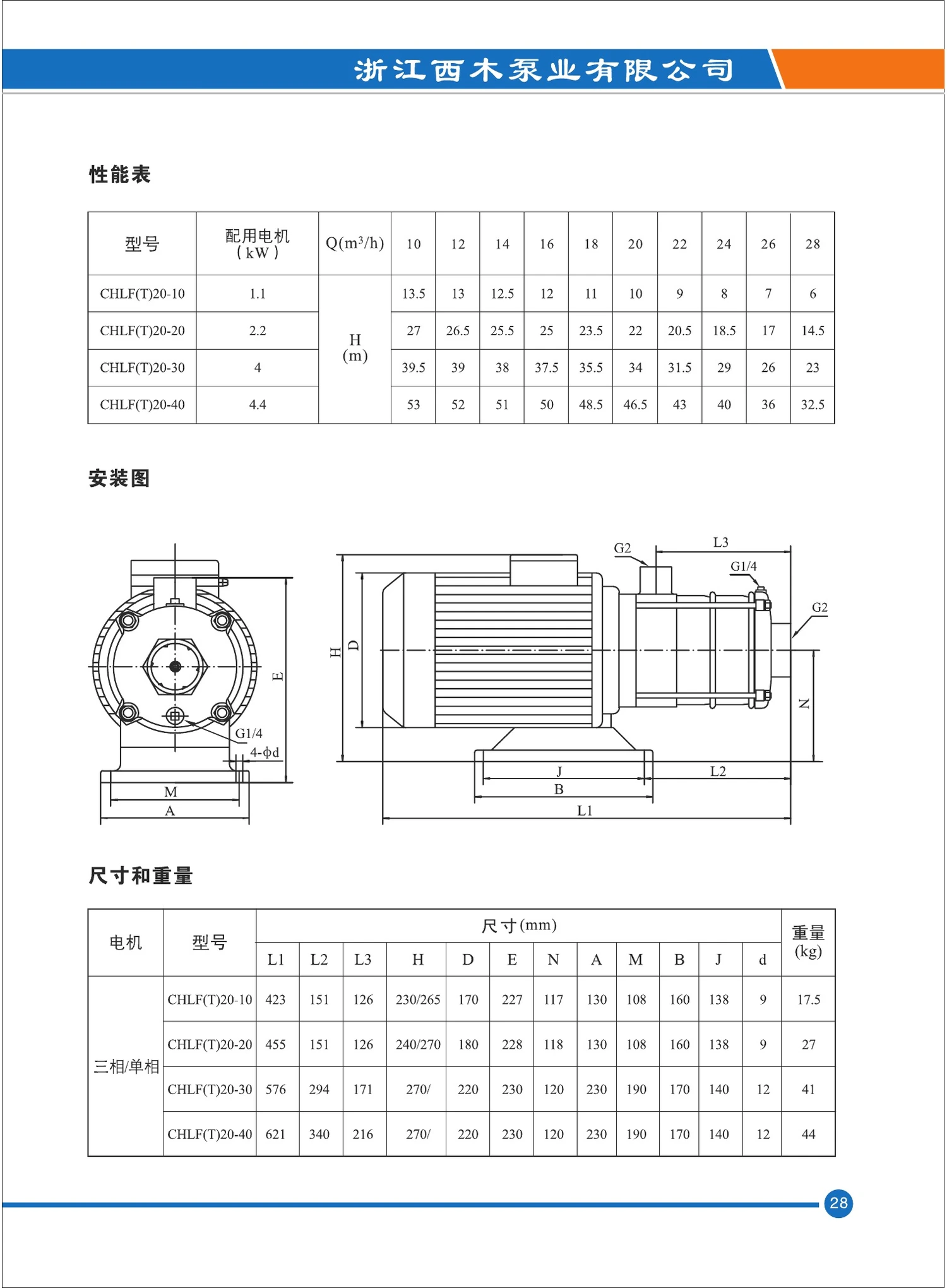
CHLF(T)20-30 sectional horizontal multistage centrifugal pump with 4 kW motor and G2 connection. At the catalog rated flow of 20 m³/h, the published head is 34 m; the displayed curve covers up to 28 m³/h and 39.5 m.
TECHNICAL DATA
Specifications, performance and construction
Confirm the final operating point, materials, motor and connection standard before ordering.
CHLF(T)20-30 product overview
The CHLF(T)20-30 is a compact non-self-priming horizontal multistage centrifugal pump for clean, thin and non-explosive liquids without solid particles or fibres. Its stainless hydraulic construction and close-coupled motor suit industrial circulation, washing, water treatment and pressure duties.
This page presents model-specific operating data, dimensions and selection information.
Model-specific technical parameters
| Model | CHLF(T)20-30 |
|---|---|
| Pump series | Sectional Horizontal Multistage Centrifugal Pump |
| Rated flow | 20 m³/h |
| Head at rated flow | 34 m |
| Motor power | 4 kW |
| Connection | G2 |
| Highest head shown on catalog curve | 39.5 m |
| Maximum flow shown on catalog curve | 28 m³/h |
| Nominal speed | 2900 / 2950 rpm |
| Frequency | 50 Hz |
Published performance points
10 m³/h: 39.5 m; 12 m³/h: 39 m; 14 m³/h: 38 m; 16 m³/h: 37.5 m; 18 m³/h: 35.5 m; 20 m³/h: 34 m; 22 m³/h: 31.5 m; 24 m³/h: 29 m; 26 m³/h: 26 m; 28 m³/h: 23 m.
Curve values are catalog test data based on clean water at 20°C with kinematic viscosity of 1 mm²/s. Select the pump near its efficient operating range and verify the complete system curve before ordering.
Operating limits and motor
| Liquid temperature, standard version | -15°C to +70°C |
|---|---|
| Liquid temperature, hot-water version | +70°C to +110°C |
| Maximum ambient temperature | +40°C |
| Maximum working pressure | 10 bar |
| Motor enclosure | Totally enclosed, fan-cooled, 2-pole |
| Protection / insulation | IP55 / Class F |
| Standard voltage | 1×220-240 V or 3×220-240/380-415 V, 50 Hz |
| Maximum single-phase motor power | 2.4 kW |
Construction and materials
| Inlet and outlet sections | AISI 304 stainless steel for CHLF; ASTM 25B cast iron inlet/outlet sections for CHLF(T) |
|---|---|
| Impellers | AISI 304 stainless steel |
| Shaft | AISI 304 stainless steel |
| Diffusers and support diffusers | AISI 304 stainless steel |
| Guide vanes / impeller spacers | AISI 304 stainless steel |
| Mechanical seal | Model-dependent mechanical seal arrangement |
| Base plate | AISI 1015 steel plate |
| Optional wetted material | AISI 316 available subject to model confirmation |
CHLF(T)20-30 dimensions and model table
The official high-resolution sheet confirms installation dimensions, port arrangement and net weight for this exact configuration.
| Dimension L1 (mm) | 576 |
|---|---|
| Dimension L2 (mm) | 294 |
| Dimension L3 (mm) | 171 |
| Dimension H (mm) | 270/- |
| Dimension D (mm) | 220 |
| Dimension E (mm) | 230 |
| Dimension N (mm) | 120 |
| Dimension A (mm) | 230 |
| Dimension M (mm) | 190 |
| Dimension B (mm) | 170 |
| Dimension J (mm) | 140 |
| Dimension d (mm) | 12 |
| Net weight (kg) | 41 |
CHLF(T) performance curves
The curve sheet shows head, absorbed power, NPSH and efficiency versus capacity for the complete CHLF(T)20 group.

Typical applications
- Air-conditioning and cooling-water circulation
- Industrial cleaning and washing systems
- Water treatment and purification
- Aquaculture and environmental systems
- Fertilization and metering-support systems
- Clean-water pressure boosting and process transfer
Selection and ordering guide
- Provide required flow and total dynamic head, including pipe and fitting losses.
- Confirm liquid composition, pH, chloride content, temperature, density and viscosity.
- Confirm normal or hot-water version, stainless grade and CHLF or CHLF(T) inlet/outlet construction.
- Confirm voltage, frequency, phase, connection standard and control method.
- Review NPSH available, inlet pressure and the 10 bar maximum working-pressure limit.
Installation and maintenance
Install the pump horizontally on a rigid level base, align piping without strain, provide isolation valves and avoid dry running. Prime the pump before start-up, verify motor rotation, and monitor noise, vibration, leakage, pressure and current. Isolate electrical power and system pressure before servicing seals, bearings or hydraulic stages.
Download complete CHL / CHLF(T) selection manual (PDF) ↓
SELECTION SUPPORT
Application-based pump selection
Send the liquid, flow, head or pressure, temperature, solids, installation, power supply and destination for a verified recommendation.
Discuss this application